gEDA Project vs Circuit Diagram

Struggling to choose between gEDA Project and Circuit Diagram? Both products offer unique advantages, making it a tough decision.

gEDA Project is a Development solution with tags like schematic-capture, pcb-layout, simulation, eda, electronics.

It boasts features such as Schematic capture, PCB layout, Circuit simulation, Netlist generation, Bill of materials generation and pros including Free and open source, Cross-platform, Full suite of EDA tools, Active community support.

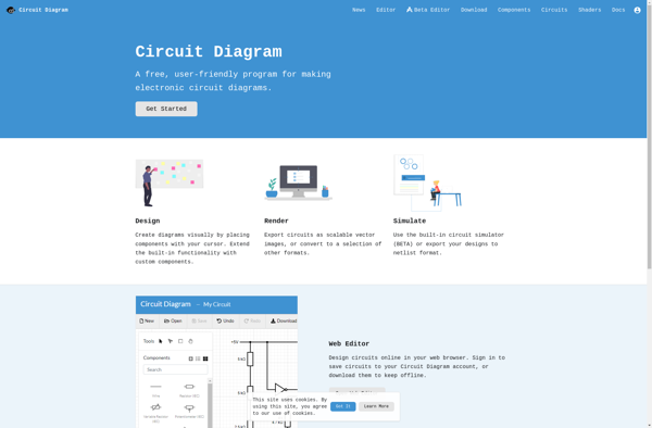
On the other hand, Circuit Diagram is a Development product tagged with circuit-design, schematics, simulation, electronics, pcb-design.

Its standout features include Schematic capture, PCB layout, SPICE simulation, Gerber output, 3D visualization, Component library, and it shines with pros like Easy to use interface, Powerful simulation capabilities, Extensive component libraries, Affordable pricing, Cross-platform support.

To help you make an informed decision, we've compiled a comprehensive comparison of these two products, delving into their features, pros, cons, pricing, and more. Get ready to explore the nuances that set them apart and determine which one is the perfect fit for your requirements.

gEDA Project

gEDA Project

gEDA is an open source suite of free software applications used for electronic design. It includes tools for schematic capture, PCB layout, simulation, and more. gEDA aims to provide a full workflow for designing and prototyping electronic hardware.

Categories:
schematic-capture pcb-layout simulation eda electronics

GEDA Project Features

  1. Schematic capture
  2. PCB layout
  3. Circuit simulation
  4. Netlist generation
  5. Bill of materials generation

Pricing

  • Open Source

Pros

Free and open source

Cross-platform

Full suite of EDA tools

Active community support

Cons

Steep learning curve

Limited simulation capabilities

Not as polished as commercial EDA tools


Circuit Diagram

Circuit Diagram

Circuit Diagram is software used to design and simulate electronic circuits. It allows users to easily create schematic diagrams, simulate circuit behavior, and export designs for PCB layout.

Categories:
circuit-design schematics simulation electronics pcb-design

Circuit Diagram Features

  1. Schematic capture
  2. PCB layout
  3. SPICE simulation
  4. Gerber output
  5. 3D visualization
  6. Component library

Pricing

  • Free limited version
  • One-time purchase
  • Subscription-based

Pros

Easy to use interface

Powerful simulation capabilities

Extensive component libraries

Affordable pricing

Cross-platform support

Cons

Limited customization options

Steep learning curve for advanced features

Only basic PCB layout tools